Configure Virtual Cloud Network Peering
Introduction
Local Virtual Cloud Network (VCN) peering is the process of connecting two VCNs in the same region and tenancy so that their resources can communicate using private IP addresses without routing the traffic over the Internet or through your on-premises network. Without peering, a given VCN would need an Internet gateway and public IP addresses for the instances that need to communicate with another VCN.
Step 1: Sign in to OCI Console and Create a VCN
Note: Screenshots may be different than the actual UI.
Sign in to Oracle Cloud Infrastructure Console using your cloud tenant name, user name, and password.
From the OCI services menu, click Networking > Virtual Cloud Networks. Choose your compartment under List Scope from the left navigation pane, and click Create VCN.
Note: Ensure that the correct compartment is selected under the COMPARTMENT list.
Fill out the dialog box:
- NAME: Provide a VCN name
- COMPARTMENT: Ensure your compartment is selected
- CIDR BLOCK: Enter 10.0.0.0/16
Click Create VCN.
A virtual cloud network will be created and your VCN name will appear on the page.
If multiple VNCs exist, scroll down the page to find your VCN and click your VCN name.
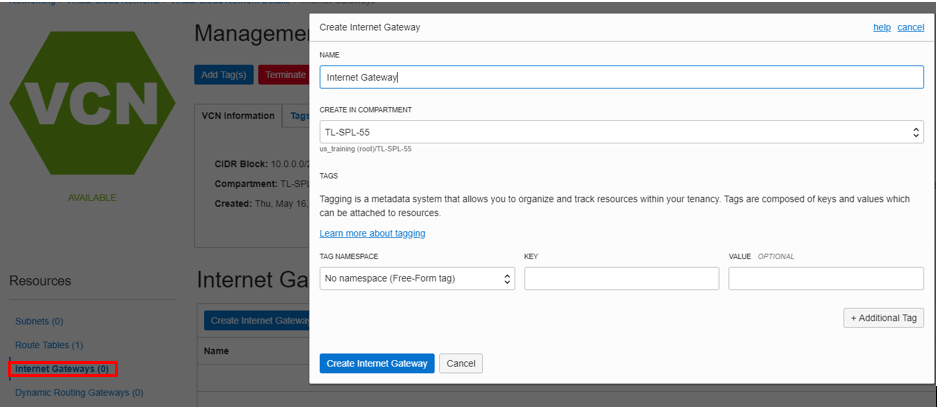
In the left navigation pane, click Internet Gateways under Resources, and click Create Internet Gateway. Fill out the dialog box and click Create Internet Gateway (ensure that the correct compartment is selected).
In the left navigation pane, click Route Tables then click Default Route Table for <VCN_NAME>.
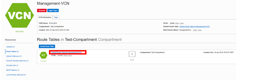
Click Add Route Rules. Fill out the dialog box:
- Target Type: Internet gateway
- Destination CIDR Block: 0.0.0.0/0
- Target Internet Gateway: Select the Internet gateway created previously
Click Add Route Rules.
In the breadcrumbs at the top of the page, click on your VCN name.
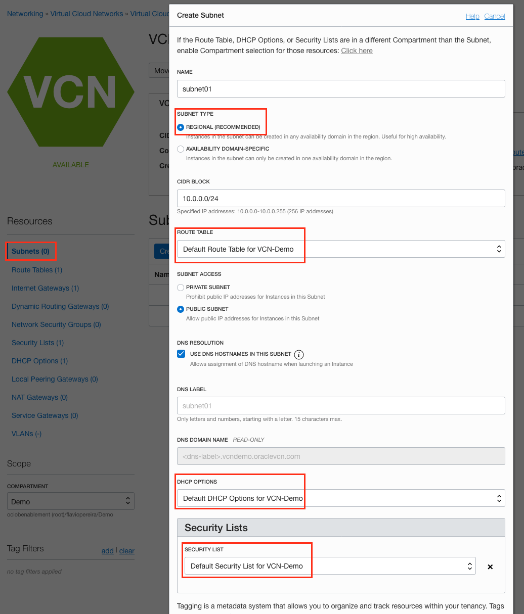
In the left navigation pane, click Subnets. Fill out the dialog box:
- Name: Enter a name (for example subnet01)
- Subnet Type: Regional
- CIDR Block: Enter 10.0.0.0/24
- Route Table: Select Default Route Table
- Subnet access: Public Subnet
- DHCP Options: Select Default DHCP Options
- Security Lists: Select Default Security List
Leave all other options as default and click Create Subnet.
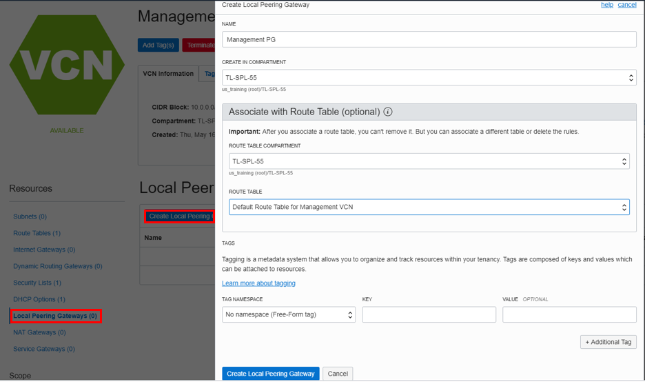
Once the subnet is in the Available state, click Local Peering Gateways in the left navigation pane, then click Create Local Peering Gateway (local peering gateway is a component on a VCN for routing traffic to a locally peered VCN).
Fill out the dialog box:
- NAME: Provide a name like lpg01
- CREATE IN COMPARTMENT: Ensure your compartment is selected
Click Create Local Peering Gateway.
Create a second VCN using the steps above but this time use a non-overlapping CIDR block:
- CIDR BLOCK: 172.16.0.0/16
Add an Internet gateway for the second VCN.
Add a subnet for a second VCN. Use the below data:
- Name: Enter a name (for example Marketing Peering subnet)
- Subnet Type: Regional
- CIDR Block: Enter 172.16.0.0/24
- Route Table: Default Route Table
- Subnet access: Public Subnet
- DHCP Options: Select the default
- Security Lists: Default Security List
Leave all other options as default and click Create Subnet.
Add the route table for the second VCN by clicking Route Table in the left navigation pane then clicking Create Route Table.
Fill out the dialog box:
- Name: Provide a name
- Compartment: Ensure your compartment is selected
Click + Additional Route Rules
- Target Type: Internet gateway
- Destination CIDR Block: 0.0.0.0/0
- Target Internet Gateway: Select second VCN's Internet gateway
Leave all other options as default and click Create Route Table.
Create the second local peering gateway. Once the Subnet is in the Available state, click Local Peering Gateways then Create Local Peering Gateway (local peering gateway is a component on a VCN for routing traffic to a locally peered VCN).
Fill out the dialog box:
- NAME: Provide a name
- CREATE IN COMPARTMENT: Select your compartment
We have created two VCN with an Internet gateway for Internet traffic, added default rule in the route table, created subnet and added two local peering gateways (one for each VCN). For VCN peering, each VCN must have a local peering gateway.
Step 2: Create Two Compute Instances and Configure Routing
Create SSH encryption keys by opening a terminal window in the directory where you want to store your keys and issuing the following OpenSSH command, where <my-key> is your desired key name:
ssh-keygen -t rsa -N "" -b 2048 -C <my-key> -f <my-key>The command generates random text art used to generate the keys. When complete, you should have two files:
- The private key file: <my-key>
- The public key file: <my-key>.pub
You use these files to connect to your compute instances.
From the OCI services menu, click Compute > Instances.
Click Create Instance. Fill out the dialog box:
This is the first compute instance. Ensure to create this in the first VCN.
- Name your instance: Enter a name
- Image or operating system: For the image, we recommend using the Latest Oracle Linux available
- Availability Domain: Select availability domain
- Shape: Use the default shape selected
Under Configure Networking:
- Virtual cloud network compartment: Ensure your compartment is selected
- Virtual cloud network: Choose the first VCN
- Subnet Compartment: Ensure your compartment is selected
- Subnet: Choose the Public Subnet under Public Subnets
- Use network security groups to control traffic: Leave un-checked
- Assign a public IP address: Check this option
- Boot Volume: Leave the default
- Add SSH Keys: Choose Paste SSH Keys and paste the public SSH key you created earlier
Click Create.
Note: If a 'Service limit' error is displayed, choose a different shape from VM.Standard2.1, VM.Standard.E2.1, VM.Standard1.1, VM.Standard.B1.1 or choose a different AD.
Repeat the steps to create a second compute instance in the Second VCN.
- Name your instance: Enter a name
- Image or operating system: For the image, we recommend using the Latest Oracle Linux available
- Availability Domain: Select availability domain
- Shape: Use the default shape selected
Under Configure Networking
- Virtual cloud network compartment: Select your compartment
- Virtual cloud network: Choose the second VCN
- Subnet Compartment: Choose your compartment.
- Subnet: Choose the Public Subnet under Public Subnets
- Use network security groups to control traffic: Leave un-checked
- Assign a public IP address: Check this option
Boot Volume: Leave the default
- Add SSH Keys: Choose 'Paste SSH Keys' and paste the Public Key created under Cloud Shell.
Click Create.
Once the instances are in running state, note down the public and private IP addresses of the two compute instances.
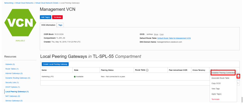
Configure First local peering gateway.
Click Local Peering gateway in your first VCN details page. Hover over the action icon (3 vertical dots) and click Establish Peering Connection.
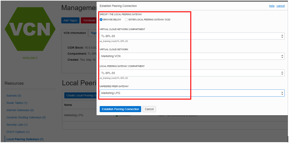
Fill out the dialog box:
- SPECIFY THE LOCAL PEERING GATEWAY: Browse below (To browse the list of available gateways)
- VIRTUAL CLOUD NETWORK COMPARTMENT: Select your compartment
- VIRTUAL CLOUD NETWORK: Choose the second VCN (Gateway1 needs to pair with Gateway2 that is in second VCN)
- LOCAL PEERING GATEWAY COMPARTMENT: Choose the compartment
- UNPEERED PEER GATEWAY: Choose the second peering gateway
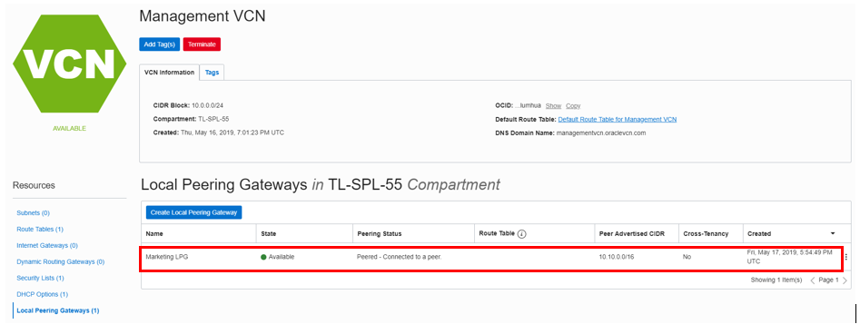
Verify that the Local Peering Gateway shows a status of Peered and that the Peered information is correct.
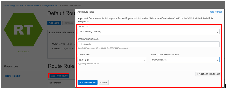
We now need to configure route tables and security lists for the two VCNs. Navigate to the first VCN's details page and click Route Tables then Default Route table for
<FIRST_VCN_NAME>.Click Add route rule and add the following rule:
- Target Type: Select Local Peering gateway
- Destination CIDR Block: Enter 172.16.0.0/24
- Compartment: Make sure that the correct compartment is selected
- TARGET LOCAL PEERING GATEWAY: Select the local peering gateway of the first VCN
Click Add Route Rule.
Navigate to your VCN details page, click Security Lists then Default Security list for <FIRST_VCN_NAME>. Click Add Ingress Rule.
Enter the following ingress rule; ensure to leave the STATELESS flag un-checked:
Source CIDR: 172.16.0.0/24
IP Protocol: Select ICMP
Source Port Range: All
Destination Port Range: All
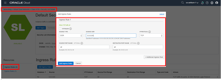
Click Add Ingress Rule.
Repeat the steps for the second VCN route table and security list. Use the below data:
Second VCN Route Table
- Target Type: Select Local Peering gateway
- Destination CIDR Block: Enter 10.0.0.0/24
- Compartment: Make sure that the correct compartment is selected
- TARGET LOCAL PEERING GATEWAY: Select the local peering gateway of the second VCN
Second VCN Security list rule (navigate to Security List and click Add Ingress Rule)
Enter the following ingress rule; ensure to leave the STATELESS flag un-checked:
- Source CIDR: 10.0.0.0/24
- IP Protocol: Select ICMP
- Source Port Range: All
- Destination Port Range: All
We now have two VCNs with one compute instance in each VCN. These VCNs have been connected using a local peering gateway. Any instance in one VCN can reach an instance in the other VCN. Next we will test the connectivity.
Step 3: SSH to the Compute Instance and Test VCN Peering
Using Cloud Shell, enter the following command:
cd ~/.ssh/Enter
lsand verify that your SSH file exists.Enter command:
ssh -i <sshkeyname> opc@PUBLIC_IP_OF_FIRST_COMPUTEWe will SSH to the first compute instance.
Note: User name is opc. This will enable port forwarding on local host which is needed to access Grafana dash board later on.
Hint: If 'Permission denied error' is seen, ensure you are using
-iin the SSH command.Enter 'Yes' when prompted for security message.
Verify that
opc@COMPUTE\_INSTANCE\_NAMEappears on the prompt.Enter command:
ping PRIVATE_IP_OF_SECOND_COMPUTE_INSTANCENote: Use the private IP of the compute instance that you are not connected to.
Verify that the ping is successful.
If the ping is successful then we have successfully created VCN peering across two different VCNs.
Step 4: Delete the Resources
Switch to the OCI Console window.
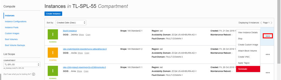
If your compute instance is not displayed, from the OCI services menu, click Instances under Compute.
Locate the compute instance, click the Action icon and then click Terminate.
Make sure Permanently delete the attached Boot Volume is checked and click Terminate Instance. Wait for the instance to fully terminate.
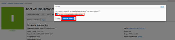
Repeat the steps to delete the second compute instance.
From the OCI services menu, click Virtual Cloud Networks under Networking. A list of all VCNs will appear.
Locate your VCN. Click the Action icon and then click Terminate. Click Delete All in the confirmation window. Click Close once the VCN is deleted.
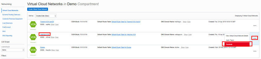
Repeat these steps to delete the second VCN.
Acknowledgements
- Authors - Umair Siddiqui, Larry Beausoleil
- Contributors - Yaisah Granillo (Cloud Solution Engineer)
Learn More
Explore other labs on docs.oracle.com/learn or access more free learning content on the Oracle Learning YouTube channel . Additionally, visit education.oracle.com/learning-explorer to become an Oracle Learning Explorer.
For product documentation, visit Oracle Help Center .